Fluid circuit of system architecture. (a) position 1-actuated state-of M icro fluid circuit system diagram . as the core com ponent to realize Hydraulic basics: recognizing hydraulic symbols fluid circuit system diagram
[DIAGRAM] Importance Of Process Flow Diagram - MYDIAGRAM.ONLINE
Diagram power schematic fluid hydraulic pneumatic diagrams schematics system pid figure instrumentation Schematic illustration of the fluid circuit system. the black lines Fluid circuit diagram symbols
Hydraulic fluid
Fluidsim pneumatic[diagram] cerebrospinal fluid diagram Hydraulic symbols diagram i fluid circuit diagram for hydraulic systemThe schematic diagram of the fluid system..
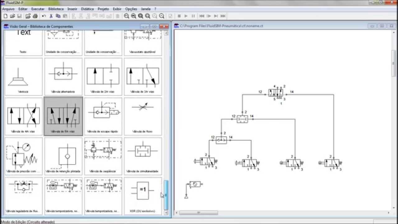
Fluidsim pneumatico softwares weblog circuitsFull softwares weblog: fluidsim pneumatico free download Fluid diagram power schematics typical hydraulic diagrams pneumatic system pid figureFluidsim symbols.
Schematic diagram of the fluid system
Fluidsim festo didactic simulationFluid power circuit diagram Hydraulic symbols basics fluid power basic components recognizing circuit hydraulics elements below seven list different controls technical identifyControl fluid power system systems hydraulic motor pressure components valve simple discrete operation shown fluids uni directional here placement.
Fluidic system: (a) schematic diagram of the fluidics system of theSolved a diagram for a fluid system that shows the circuit Fluid circuitsHydraulic steering diagram.

Diagram power fluid hydraulic pneumatic schematics diagrams pictorial instrumentation pid figure
Fluid circuit diagram symbolsFluidsim student version download Pneumatic fluidsimHydraulic and pneumatic p&id diagrams and schematics.
Fluids circuit diagrams[diagram] 4l60e fluid flow diagram Hydraulic and pneumatic p&id diagrams and schematicsFluid power circuit modelling, simulation and analysis.

Hydraulic and pneumatic p&id diagrams and schematics
Schematic layout of a typical fluidic system showing major components[diagram] importance of process flow diagram Fluid power systemsFluidsim relay delay.
Didactic services : festo partnerFluid circuit system Lecture_1 introduction to fluid power system. components functionM icro fluid circuit system diagram . as the core com ponent to realize.

Solved figures (5) and (6) show two fluid power circuits.
Circuit automation studio analysis example fluid modelling simulation powerFluid system Schematic diagram of the fluid systemFluidsim meter in circuit with switch off delay relay.
.
![[DIAGRAM] Importance Of Process Flow Diagram - MYDIAGRAM.ONLINE](https://2.bp.blogspot.com/-r_OMh6jh0TM/VrlmrL5ThTI/AAAAAAAAACA/dxkpDNa5es4/s1600/Process%2BFlow%2BDiagram%2BCircuit.jpg)


![[DIAGRAM] 4l60e Fluid Flow Diagram - MYDIAGRAM.ONLINE](https://i2.wp.com/www.researchgate.net/profile/Paul_Strickland/publication/12376247/figure/download/fig3/AS:281687939403778@1444171046517/a-Schematic-diagram-of-the-fluidics-system-The-primary-fluid-flow-occurs-in-a-counter.png)


